

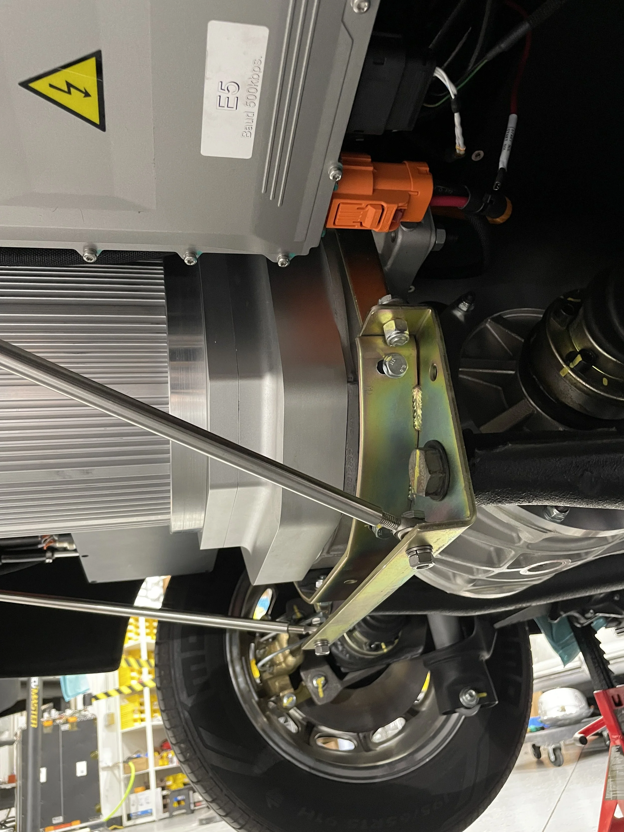
To add another mounting point for the rear of the body, we’ve added support struts that link the motor mount to the rear. This will minimize the flex that happens at the rear firewall due to the added weight of the motor.
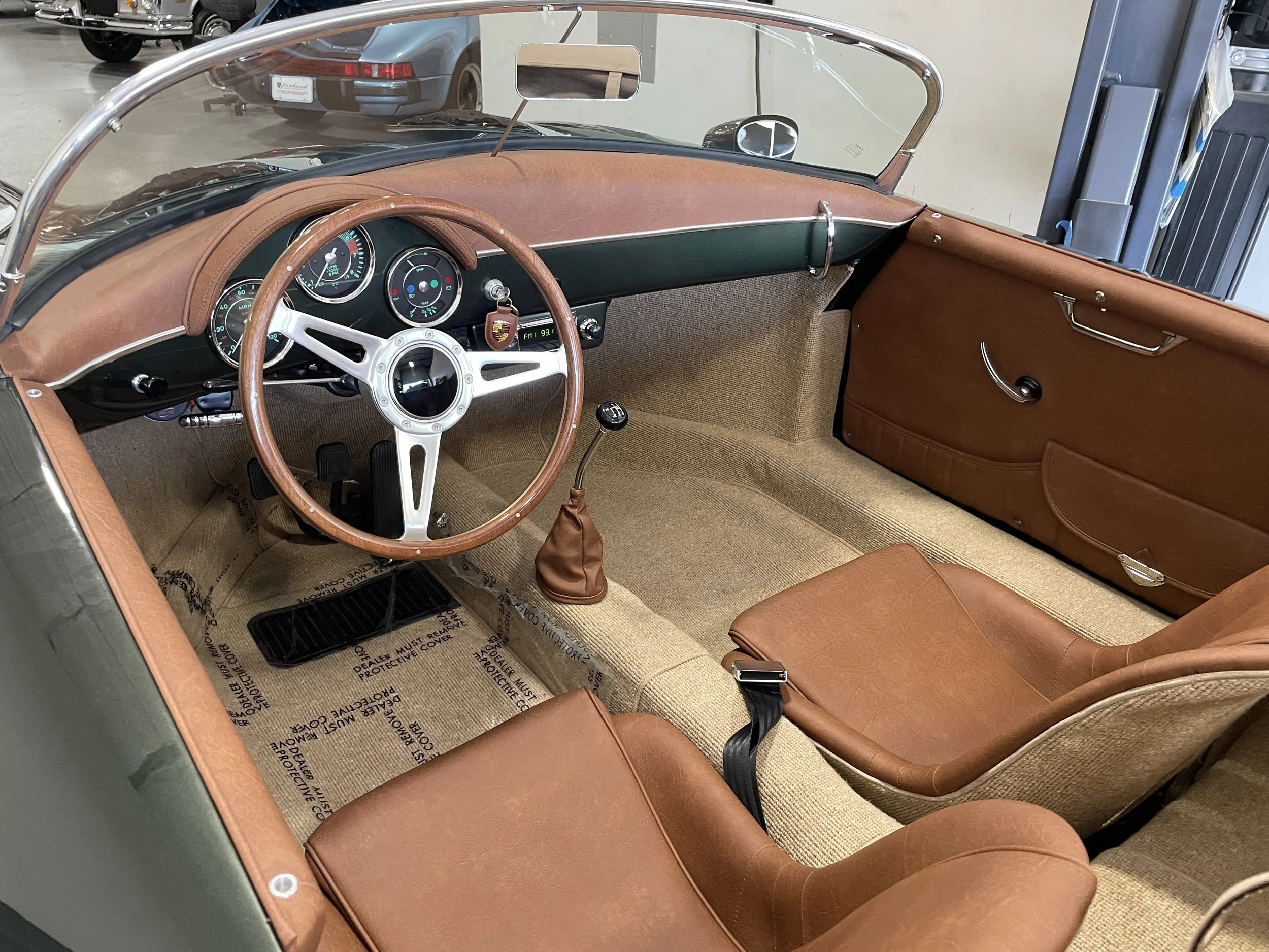
Since the shifter is in charge of the two forward speeds. We needed a selector for forward and reverse. We installed a matching push/pull style knob. We chose the milled knob to differentiate from the wiper and light switches.
The throttle pedal bracket is back from powder coat and permanently installed.
Charge port bracket coated and installed! Charge port is now secured.

Gauges have been rewired for the dashbox, and have been reinstalled. The dashbox translates vehicle control, state of charge, temperature, rpms, and various other signals to work with the “old school” instrumentation. This is stylistically consistent with the car and helps retain that nostalgic driving experience - the whole reason we do what we do. That said, sometimes it’s nice to have a more accurate and information-rich source of data so we install the Dilithium display to provide that reference.
We’ve desiging and testing the charge port bracket. This is the current solution being tested with a 3D printed version. This position makes for easy access and is the most discreet in the engine bay.
Here is the proposed Dilithium display mount. This seems like the best position which makes it easily visible and avoids the need for a larger center console mount. It also uses the existing shifter mount bolt so no further modification is needed.
As we mentioned, there are still some details we need to attend to. Above is the circular display bracket being test mounted. There’s still some discussion on if the round motor display will remain under the dash. They’re also working on the PRND switches mount along with the Dilithium display which will be in the shifter area. Below is the updated throttle position switch bracket. The previous bracket had the sensor in a different position that we didn’t prefer. Both these brackets will be laser cut and then coated to match the rest of the hard parts in the Speedster.
We made it to the Porsche meet at Mozart’s Coffee. Lots of attention and positive buzz. Tom says his voice became hoarse from answering everyone’s questions about the Speedster. It’s back at the shop now and we’ve got some final details to attend to and then it will go through our official test and tune process.
Big milestone here! Still lots of fine tuning to do but this is always a great feeling.
Through some fortunate circumstances and a very committed technician, we were able to focus on assembling the car and get it running by the end of the week. Our powder coater agreed to expedite all the hard parts we needed, and from there it was getting everything out of the car, then back in, and mounted. Once all the major vehicle control components were in they got to work waking the car up. Since we had the motor running on the bench, the wake up process is a little quicker but it still involves sorting any wiring issues and making sure everything is in working order. Normally testing and tuning is a month long process once the car is driving, so we’ll likely need a few more weeks to make sure the Speedster is running perfectly.

We finished connecting most of the main HV wiring. The lines from the battery boxes to contactor box, and contactor box to inverter are terminated and connected. The motor phase leads are also connected. The only HV wiring left to run is to the DC/DC converter and the charging circuit.

We focused on getting the vehicle control harness laid out and routed this week. What starts out as single strands of military specification wire, becomes an array of circuits that will lay hidden away. Milspec connectors, harness construction best practice, and hot rod aesthetic sense culminate in a reliable harness that is easily serviceable if needed. Above is the loomed harness ready to be routed. Immediately below is the colorful construction in progress. In the last pic you can see a branch of the harness laid in the car and terminating at the PMU.


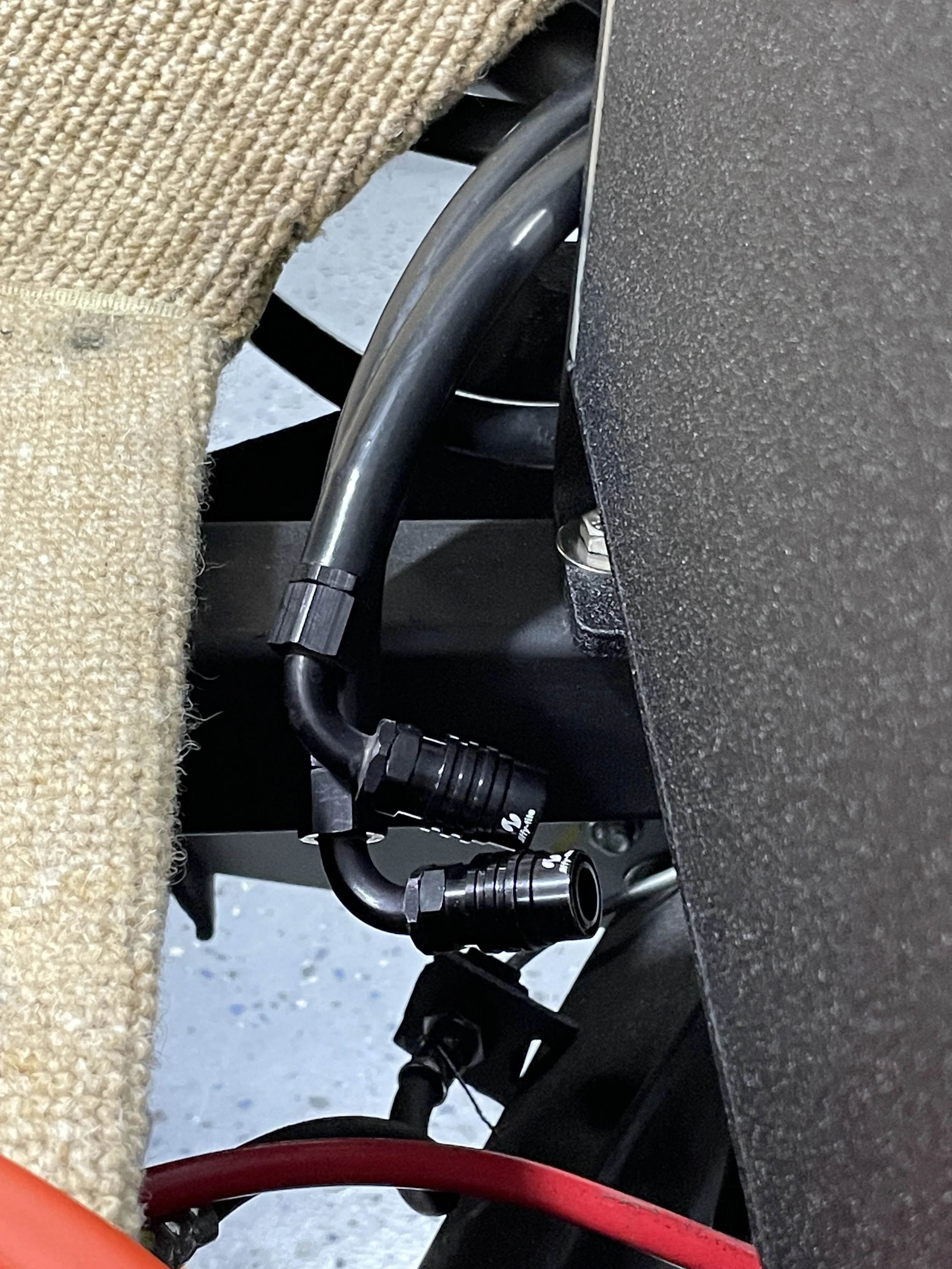
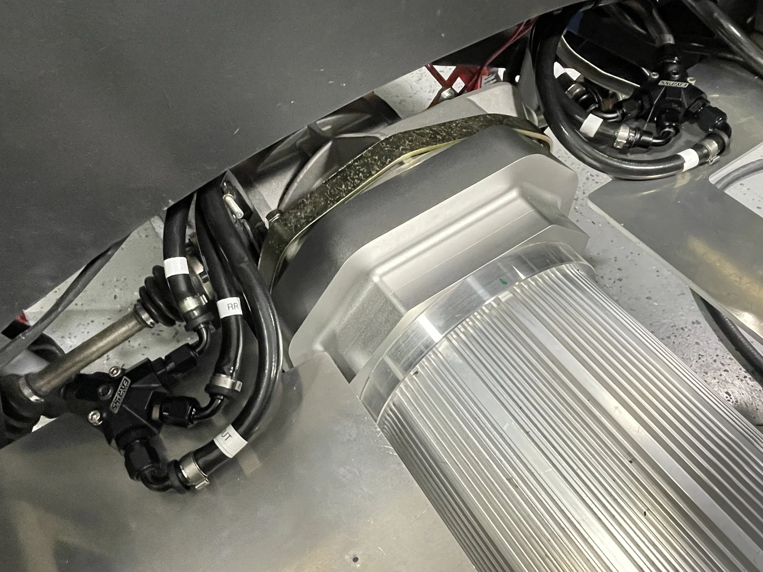
We spent a lot of time on the cooling system this week. The soft lines to the mid and rear battery boxes are terminated. The manifolds that split the circuit to their separate branches are in. The hard lines to the coolant reservoir are also complete and connected. The quick release fittings you see above and below are pretty neat. They have valve feature that cuts the coolant flow off when the fittings are disconnected. Very convenient when you’re working on the system or in the rare case, needing service.
The frunk cover plates are in and fit great.
They’ve bent and routed the coolant hard lines front to rear. They’ll couple those to the soft lines which will terminate at various locations to complete the cooling circuit.
We test fit the on-board charger and DC/DC inverter on their mounting plate. Similar process here, where they verify placement, check that coolant and electrical circuit routing is ideal, then they’ll remove everything to prep the plate for coating.
They mounted the cooler, coolant pump, and reservoir to assist with coolant line routing this week. Above is the new Chase Bays reservoir, below is the coolant pump and finned cooler. They’ll start bending hardlines next and mounting them up.
This week we also started laying out the Vehicle Control Harness, separating each bundle of wires out so they can be run to their final destinations. Some go to the throttle, some to the dashboard for direction control, and others to the contactor box to control current flow, etc. These will then be cut to length, pinned to their corresponding connector, and loomed and routed through the car.
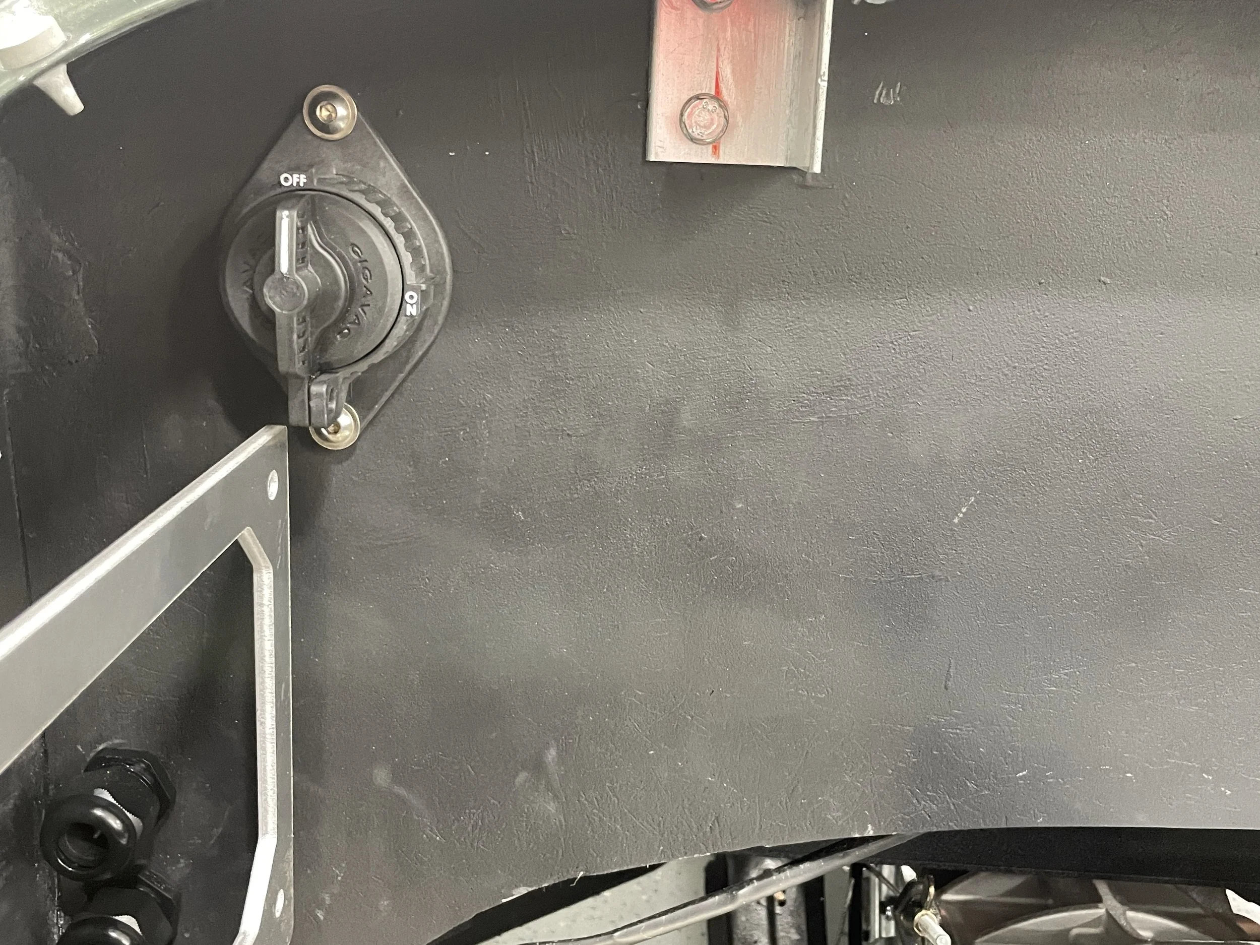
Master HV cut off switch is at home in the engine bay. This will stay off until they’re ready to wake the car up. Then on this is only used for service if necessary.